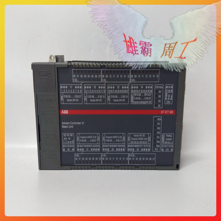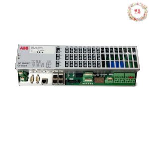
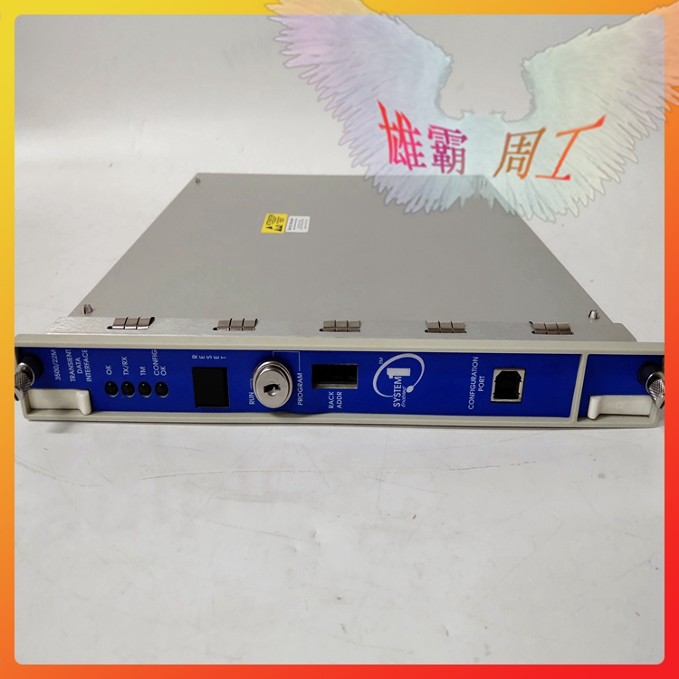


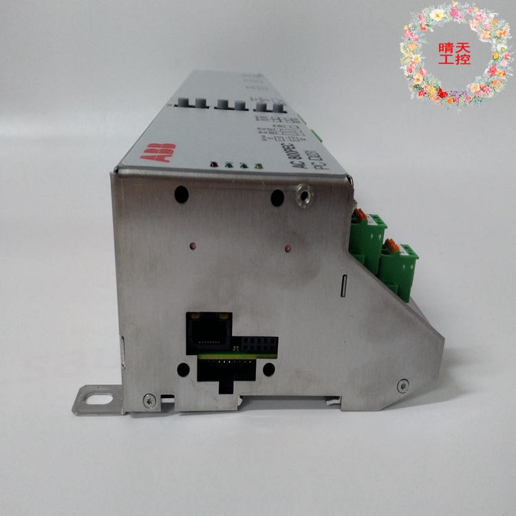
PCD231B101 3BHE025541R0101 ABB exciter control module
Brand ABB Color Standard Application Industrial height 238mm rated current 280mA
Protection Level IP45 Suitable for motor power 129KW Application Site Power Industry Material Code GJR2391500R1220 Power industry HIEE401782R0001 Part Number PCD231B101 3BHE025541R0101
Applicable pipe 2 Whether imported is weighing 3.66 kg can be sold nationwide
PCD231B101 3BHE025541R0101 ABB exciter control module
ABB excitation control module PCD231B101 3BHE025541R0101
ABB excitation control module PCD231B101 3BHE025541R0101
ABB excitation control module PCD231B101 3BHE025541R0101
Use the thermal relay to make the limiting circuit
Thermal relays are mostly used for motor overcurrent protection, but they can also be used as limiters in some collective power units or places. The specific production method is shown in Figure 24. When the thermal relay is manually reset, unscrew the thermal relay reset screw. The rated current of the selected thermal relay is consistent with the total rated current of the user.
FIG. 24 Use of thermal relays to make a cut-off circuit
25. Two self-mounting AC power supply phase sequence indicators
A small power supply phase sequence indicator can be formed by using resistor, capacitor and neon bubble. When the power supply is connected according to L1, L2, L3, neon lights will be on; Neon lights are not on when L2, L1, and L3 are connected in reverse phase sequence. The circuit is shown in Figure 25(a).
The second method is to use a 2μF, 500V capacitor and two incandescent bulbs of the same power (220V/60W) to make an AC power phase sequence indicator, see Figure 25(b).
Figure 25 Two self-contained AC power supply phase sequence indicators
Working principle: Due to the capacitor phase shift, the phase difference of one of the phases is changed, and the vector voltage on HL1 and HL2 is different, and the law is that L2 phase vector voltage is greater than L3 phase vector voltage. Therefore, after connecting according to Figure 25(b), the capacitor is connected to the L1 phase of the power supply, so it can be seen that the end of the lamp with strong light is L2 phase, and the end with weak light is L3 phase.
26. Two methods for measuring the head and tail of the three-phase winding of the motor
When the 6 lead line marks of the motor cannot be confirmed, we can use the AC power supply and the lamp to check the head and end of the three-phase winding of the motor to avoid misconnecting the winding.
Figure 26 Two methods for measuring the head and tail of the three-phase winding of a motor
The method of determining the three-phase winding of the motor with the AC power supply and the lamp is: first, the 36V low-voltage lamp is used as a test lamp, the two wire ends of each phase coil of the motor are separated, and then the two-phase coil is connected to the 220V power supply after the two ends of the remaining phase coil are connected to the 36V lamp line into the power supply, the lamp is bright, indicating that the two phases in series are connected to each other. If the bulb does not light, it means that the heads are connected, as shown in Figure 26(a). Then the measured two-phase coil head and tail make a mark, and then according to this method, one of the phases is connected to the original bulb coil in series, the other phase is connected to the bulb, and then according to the same reason, the motor three-phase winding head and tail is easy to distinguish.
Another method is to use a multimeter to determine the motor’s three-phase winding head and tail, first use a multimeter to measure which two wire ends of the six wiring ends of the motor are the same phase, and then switch the DC milliamp gear of the multimeter to the smallest gear, and connect the pen to a group of two ends of the three-phase winding, and the battery positive and negative poles to the two wire ends of the other phase. As shown in Figure 26(b), when the switch S is closed, if the pendulum of the watch hand is greater than zero, it means that the wire end connected to the negative electrode of the battery and the wire end connected to the positive pen of the multimeter are of the same polarity (can be considered as the head). By doing so, the head and tail of the other two phases can be measured.
27. Use headphones and light bulbs to form a simple line breaker
Figure 27(a) and (b) show the simplest line break detector. When the wire path is measured, the bulb will glow, and the headset will ring at the instant of on-off; When the line is disconnected, the headset does not ring and the bulb does not light. This method is simple and easy, and is very suitable for beginner electricians to make tools and meters or to replace multimeters for measurement, and its advantage is convenient to carry.
Figure 27 A simple line breaker composed of earphones and light bulbs
28. A simple method of measuring wire connection
FIG. 28 shows an induction pen circuit. It can easily measure the broken core position of the wire. When it is used to measure the location of the broken core of the wire, connect the 220V power phase wire at one end of the wire, and then use the probe gate of the induction measuring pen to approach the measured wire and move along the line. If the light-emitting diode is suddenly extinguished while moving, then this is the location of the conductor’s broken core.
FIG. 28 A simple connection method for measuring the connection of wire
29. Use a line lamp transformer to boost or reduce voltage
Figure 29 A method of boosting or reducing voltage with a line lamp transformer
In some places, because the network voltage is low for a long time or due to the reduction of electricity consumption at night, the network voltage rises, some electrical appliances cannot work normally or are damaged, and the use of line lamp transformers to boost or reduce voltage can meet the needs, see Figure 29.
The use of this method should pay attention to two points: first, before wiring must be the secondary end of the lamp transformer and the housing of the connection wire (protective grounding wire) removed; The second is to pay attention to the current of the primary and secondary windings of the lamp transformer can not exceed their respective rated current values.
30. A simple method for checking thyristors
The thyristor can be checked using the simple method shown in Figure 30. When the switch S is off, the bulb is not bright, and when the switch S is closed, the bulb is bright, indicating that the thyristor can work, otherwise the thyristor is bad. This method can be tested for general thyristors, and the light bulb is a 1.5V small electric bead bulb.
Figure 30 A simple method for checking thyristors
31. Use the welding machine to dry the motor line
If the motor is damp and the volume is large, it is not easy to disassemble and dry in the oven. The welding machine can be low-voltage electric into the three-phase winding of the motor, and the motor can be dried by current heating. This method is suitable for drying 20~60kW motor, the capacity of the welding machine should be selected according to the capacity of the motor. The current through the motor winding coil can be adjusted by the welding machine, but in the drying should be noted that the current through the motor can not exceed the rated current of the motor itself too much, and pay attention to observe that the motor and the welding machine temperature can not rise too high. The circuit is shown in Figure 31.
Figure 31 Drying motor lines with an electric welder
32. Transformer short circuit drying method
Short-circuit the winding of the transformer on one side, apply voltage with the autotransformer on the other side, so that the rated current flows through the winding of the transformer, and rely on the heat generated by the winding copper loss (I2R) to heat the transformer, the purpose of drying the transformer can be achieved, as shown in Figure 32.
The method is simple and practical, and the drying temperature is fast. However, the capacity of the autotransformer is also larger, generally more than 10% larger than the capacity of the transformer to be dried. In addition, this method is also easy to produce local overheating, and the power consumption is large, so it is generally only suitable for drying transformer capacity is not large.
For safety reasons, the voltage is generally applied from the low voltage side of the transformer, and the high voltage side is shorted. For a three-winding transformer, only one winding can be connected to the power supply, the other is short-circuited and grounded, and the third winding should be open. Using the short-circuit drying method, it should be noted that the current on the short-circuit side should not exceed the rated current on the side too much.
Figure 32 Transformer short-circuit drying method
33. Use transformers wisely
In some areas, the voltage is often below 220V; In some areas, the voltage is higher than 220V; Then the existing double-winding transformer is connected into an autotransformer to raise or lower the power supply voltage; That is, the electrical appliances with rated voltage of 220V can work normally; As shown in Figure 33. When the switch S is in the “boost” position; The transformer is equivalent to an autotransformer; Increase the supply voltage by 6.3V; If the switch S is hit in the “normal” position; The load is directly connected to the power supply; The output voltage remains the supply voltage. The black dot in the figure represents the end of the winding with the same name. If the primary and secondary connection lines are connected by the same name; The output voltage will be reduced by 6.3V. Adopt this connection; The load current shall not be greater than the primary and secondary rated current. The network voltage is often 30 ~40V lower (or higher) than 220V; Optional 220V/36V transformer connection.
PCD231B101 3BHE025541R0101 ABB exciter control module
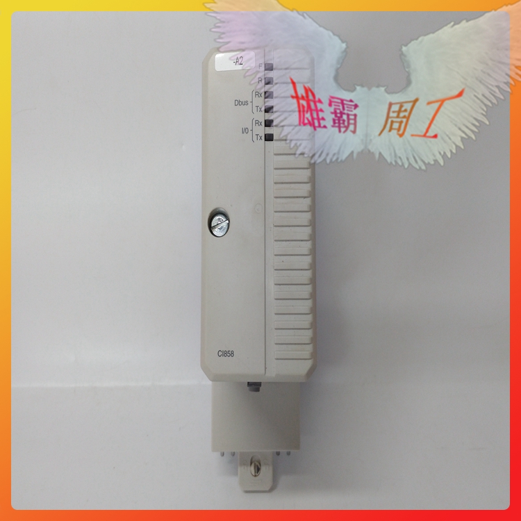
ABB CI868K01-eA
ABB CP430T-ETH
ABB D2D146-AA28-28
ABB DAI03
ABB DAO01
ABB DDI01
ABB DDO01
ABB DLM02
ABB DSAI133A
ABB DSDO115A
ABB DSDX453
ABB DSPC454
ABB DSQC332A
ABB DSQC504
ABB DSQC509
ABB DSQC633
ABB DSRF197K01
ABB DTCC901B